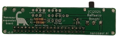
Expansion board
If you want buy the Nanosaur expansion board or you want support this project, please consider to watch the PCB project.

The Nanosaur Expansion-board is under license Creative Commons Attribution-NonCommercial-ShareAlike 4.0 International License.
The expansion boars has size 20mm x 80mm and have four M2 mounting holes, that perfectly fit inside the Nanosaur flap.
This board is a simple adapter to connect the motor controller and the LCDs to the NVIDIA Jetson on your nanosaur, this board connect:
- I2C bus 0 (Pin 27, 28)
- oled right
- I2C bus 1 (Pin 3, 5)
- oled left
- adafruit motor control
- 2 custom buttons
- GPIO Pin 31
- GPIO Pin 33
How make Nanosaur PCBs on PCBWay
- Register to PCBWay using my refferer link
- Upon you registered, go to the nanosaur
- Click on “Add to Cart” button on the right
- A pop-up will show up: all default settings are good. You must only select how many PCBs you want: the minimum quantity, by default, is 5. The first order of 5 PCBs is free on PCBWay: you must pay only the shipping costs
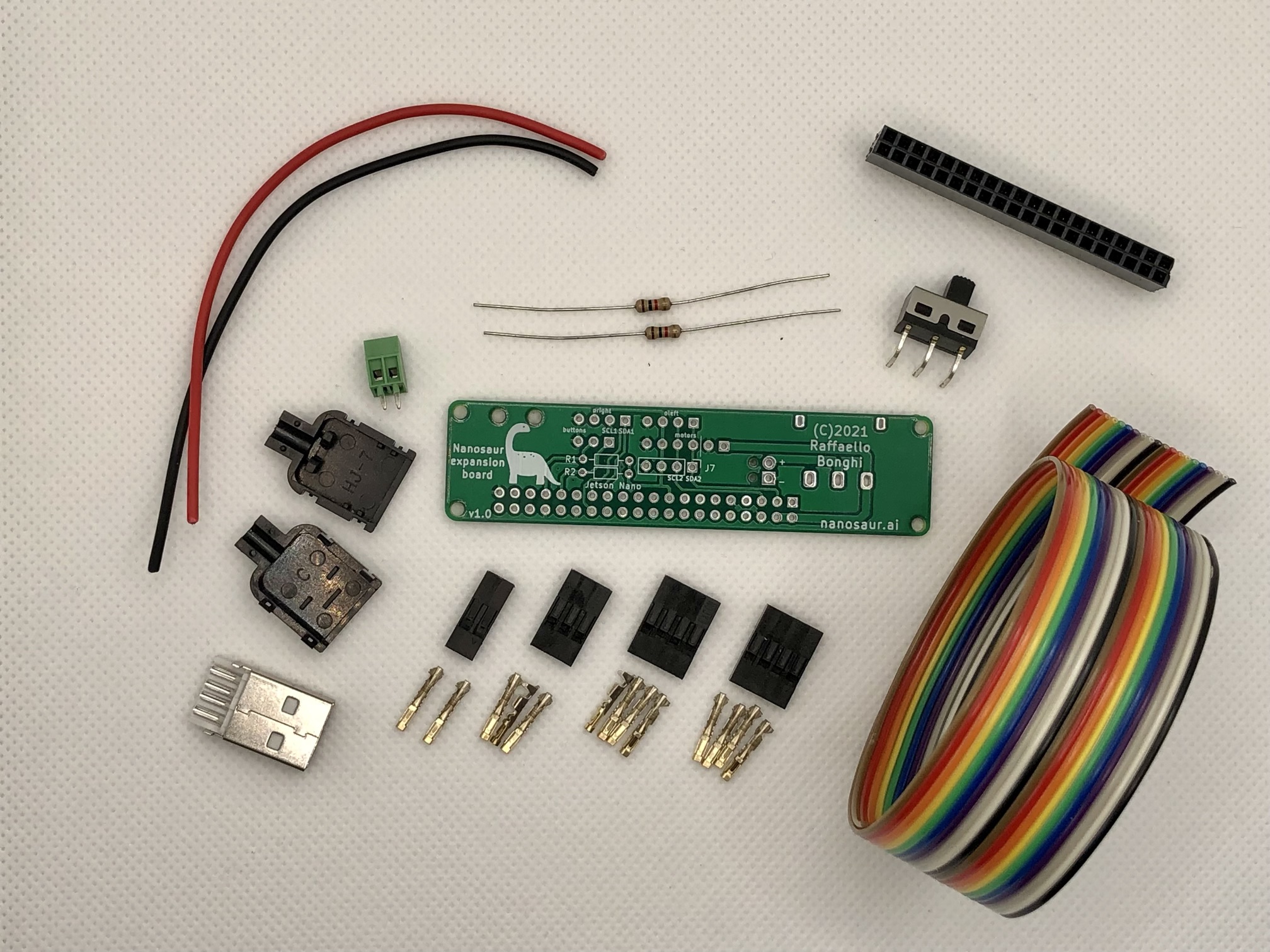
Components
The list of components that you need to have are in this table below
| Ref | Qt | Value | Component | Note |
|---|---|---|---|---|
| J1 | 1 | jetson_nano | PinHeader 2x20 - P2.54mm | aliexpress.com |
| J2 | 1 | Screw_Terminal_01x02 | Terminal block 1x02 - 2.54mm | aliexpress.com |
| J3 J4 | 2 | Conn_i2c_oled | cable 1x4 length 300mm | Read Table connectors |
| J5 | 1 | Conn_motors | cable 1x6 length 210mm | Read Table connectors |
| J6 | 1 | Conn_buttons | cable 1x3 length 300mm | Read Table connectors |
| J7 | 1 | Conn_01x04 | Pin Header 1x3 (optional*) | |
| R1 R2 | 2 | 1k | Resistor THT 1/4W (optional*) | aliexpress.com |
| SW1 | 1 | SW_SPDT | Slide switch P4.7mm | aliexpress.com |
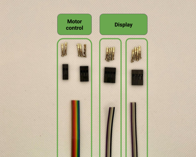
![]() Hint Reference Table connectors
Hint Reference Table connectors
If you BoM have all components, like the picture below you are ready to assembly!
Schematic
This expansion board is a simple connector for oleds and motor controller and works taking the power from the Power bank and power up the robot passing from a slide switch.
More detail are available on nanosaur expansion board schematic.

![]() Download the nanosaur expansion board nanosaur-schematic.pdf
Download the nanosaur expansion board nanosaur-schematic.pdf
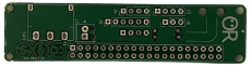
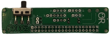
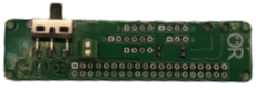
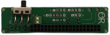
Assembly PCB
To assembly the PCB, you need only a solder all components and follow the steps on the gallery below.
- Resistors
- Switch
- Terminal block 1x02
- PinHeader 2x20
The PCB will be like the last picture of the gallery
Wiring PCB
To wire bring your 30cm flat ribbon cable 20P Rainbow IDC wire 1.27mm and split in 3 different wires:
| Quantity | Name | Length | Color code |
|---|---|---|---|
| 1 | Conn_motors | 210mm | brown -> blue |
| 2 | Conn_i2c_oled | 300mm | violet -> black |
| 2 | motor | 90mm | red & brown |
| 1 | USB connector | 120mm | black & red |
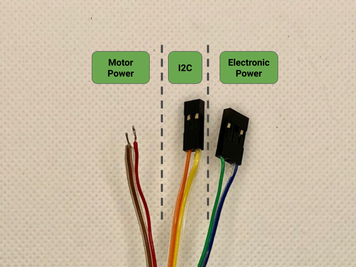
Now pay attention to wire in the right order the motor control cable (Conn_motors) where:
| Num | Color | Connection | Type |
|---|---|---|---|
| 1 | brown | spare | Motor (+) |
| 2 | red | spare | Motor (-) |
| 3 | amber | 2Pin Dupont connector | SDA |
| 4 | yellow | 2Pin Dupont connector | SCL |
| 5 | green | 3Pin Dupont connector side | VCC (+3.3V) |
| 6 | blue | 3Pin Dupont connector side | GND |
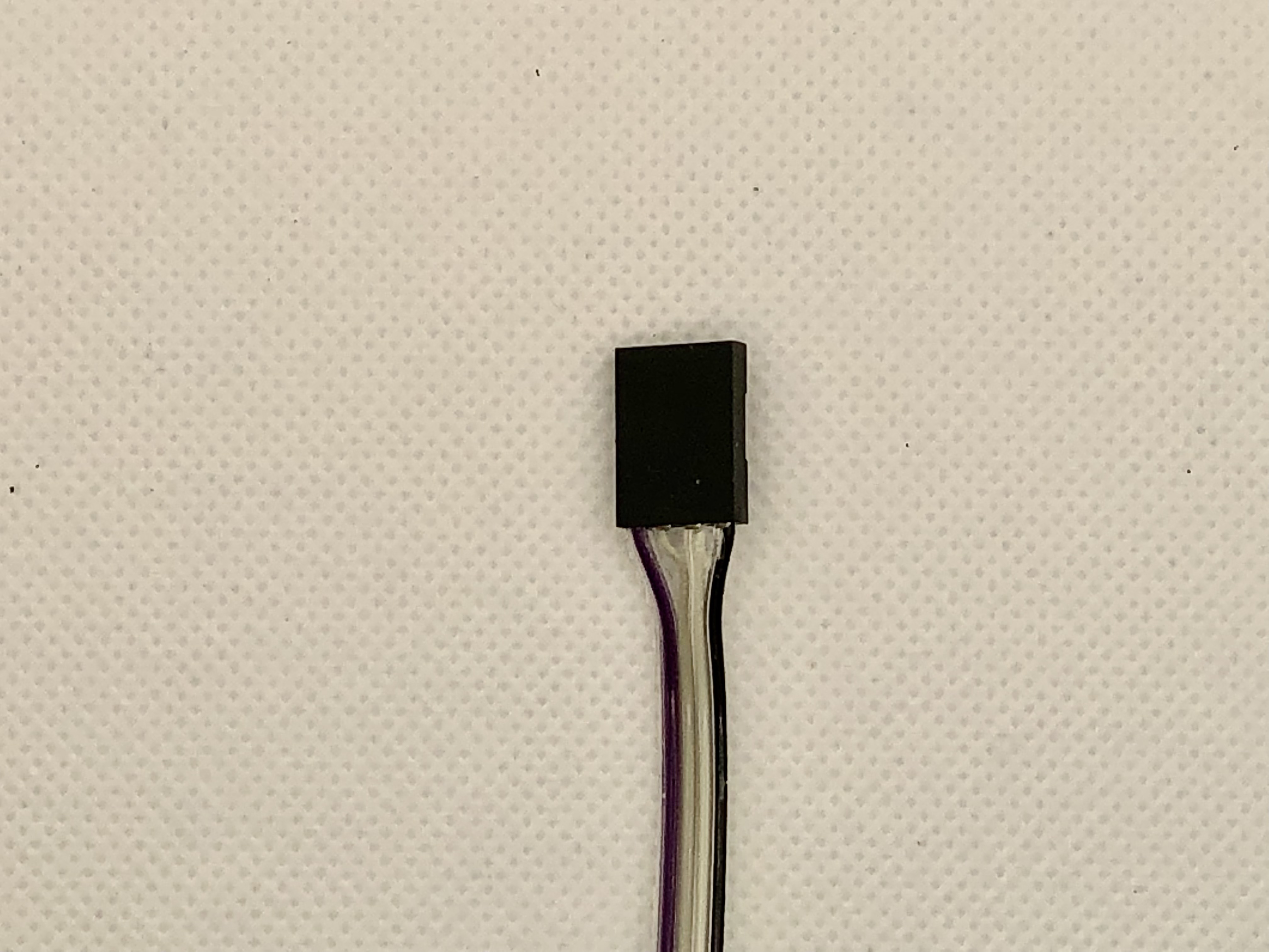
For the both display follow this table
| Num | Color | Connection | Type |
|---|---|---|---|
| 1 | black | 2Pin Dupont connector | GND |
| 2 | white | 2Pin Dupont connector | VCC (+3.3V) |
| 3 | grey | 2Pin Dupont connector | SCL |
| 4 | violet | 2Pin Dupont connector | SDA |
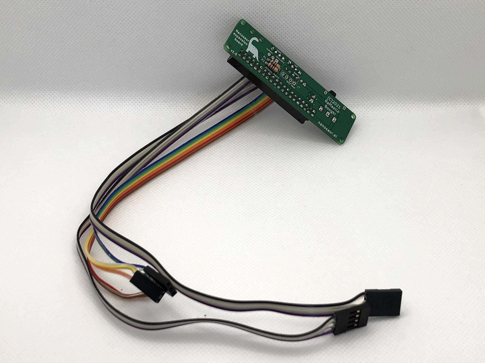
The wiring will be like the pictures below:
To wire the expansion board follow the picture below, where:
| Plug | Name | Note |
|---|---|---|
| J3 | Conn_i2c_oled right | Violet wire on squared hole (pin 1) |
| J4 | Conn_i2c_oled left | Violet wire on squared hole (pin 1) |
| J5 | Conn_motors | Brown wire on squared hole (pin 1) |
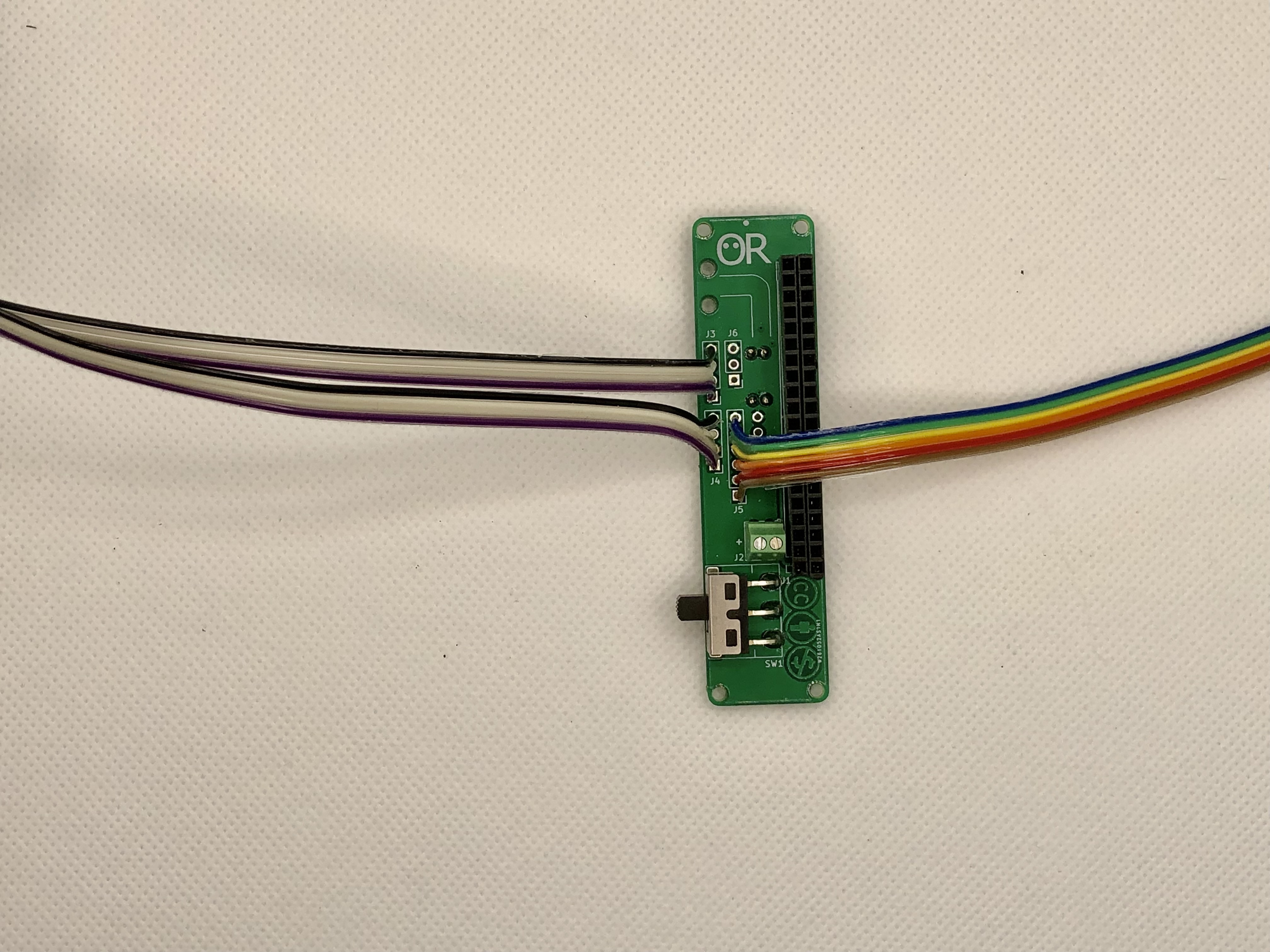
When the soldering is done you will obtain nanosaur expansion board ready to be assembled on Nanosaur
Wiring USB connector
Last plug, last wiring! It’s almost done.
Bring your 120mm wires red and black and solder to the USB connector following the USB pinout below
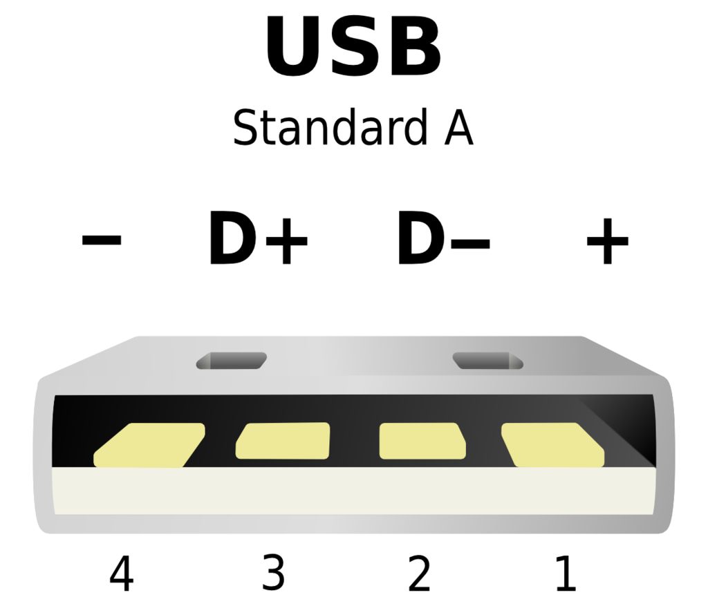
Now wire the USB connector follow this table
| Num | Color | Type |
|---|---|---|
| 1 | red | + |
| 2 | - | D+ |
| 3 | - | D- |
| 4 | black | - |
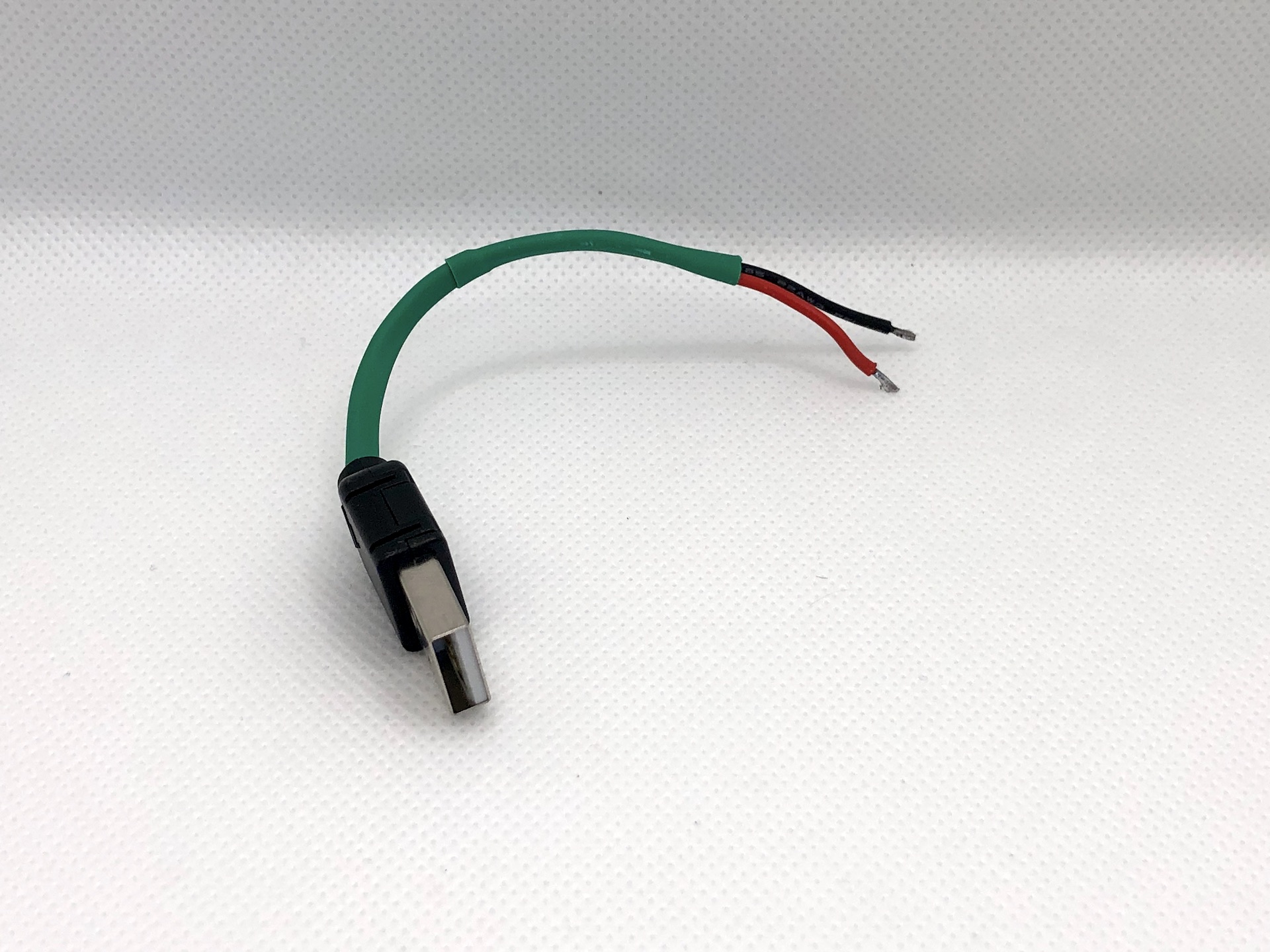
And follow the pictures below to make your USB wire for the Nanosaur expansion board.

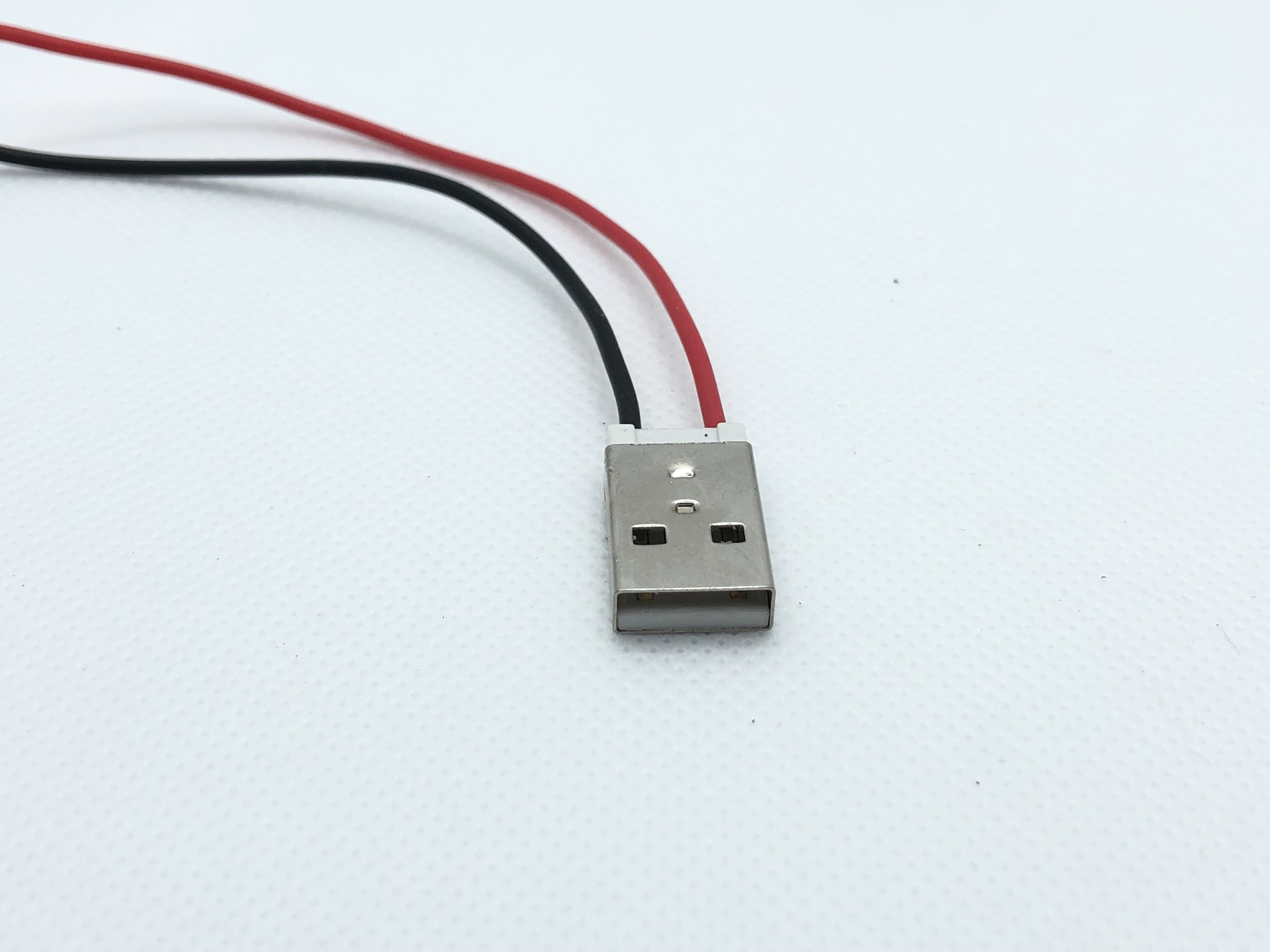
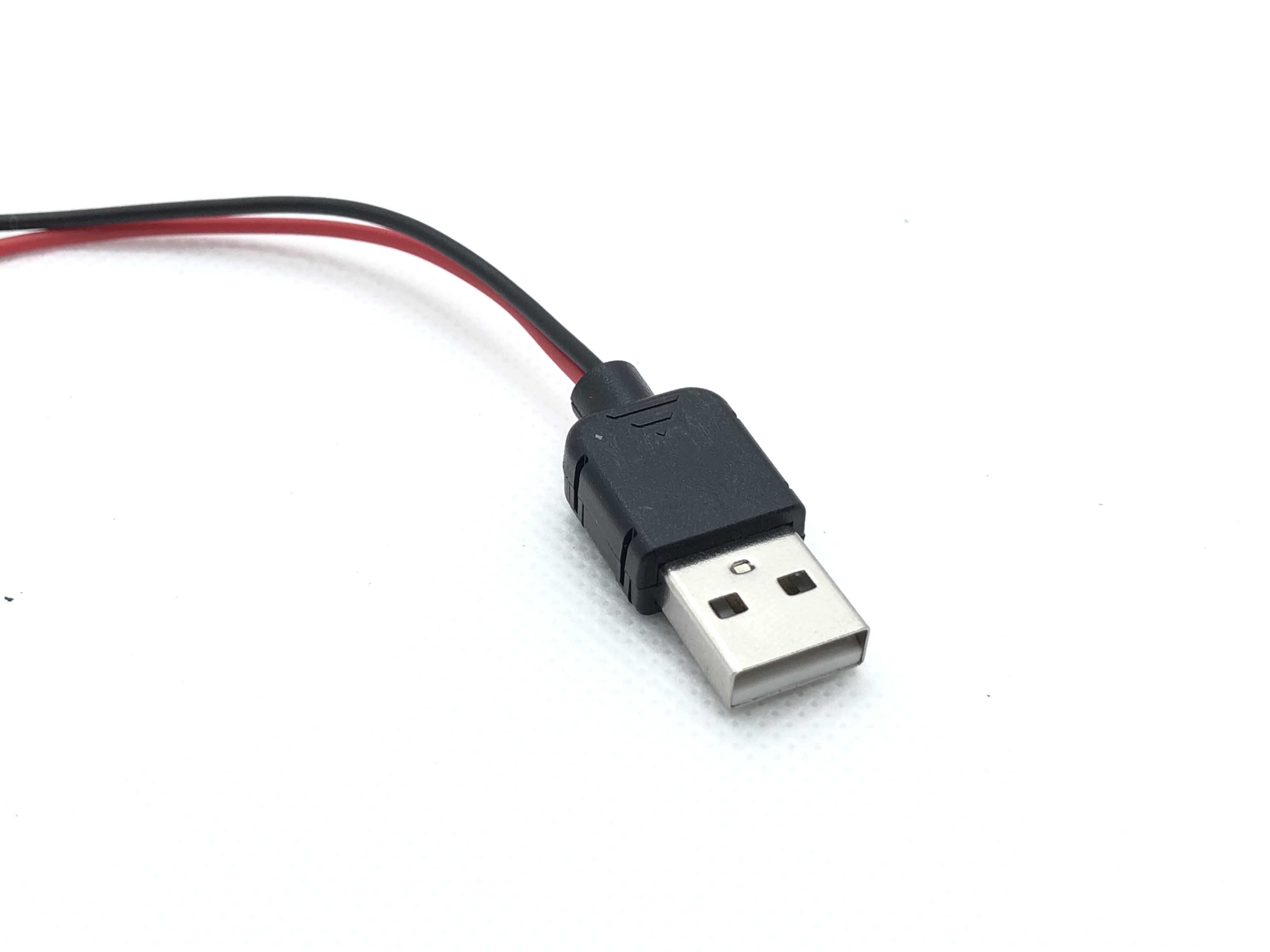
Add an heat shrink to insulate the wires and the connector will look like the picture below
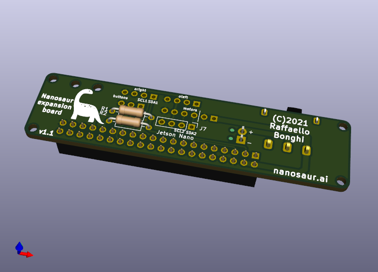
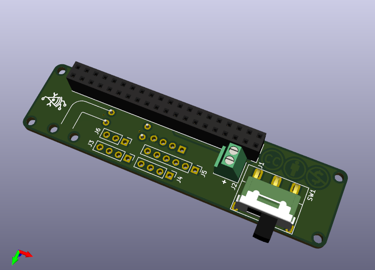
PCB Board
The Nanosaur Expansion-board is under license Creative Commons Attribution-NonCommercial-ShareAlike 4.0 International License.
The size is 20mm x 80mm with 4 M2 mounting holes, with PCB Layout will be like the pictures below


![]() Download the Nanosaur expansion board STEP file nanosaur-exp-board.step
Download the Nanosaur expansion board STEP file nanosaur-exp-board.step
If you want print by yourself the expansion board, you can download the gerber file from this link
![]() Download the Nanosaur expansion board gerber file nanosaur-gerber.zip
Download the Nanosaur expansion board gerber file nanosaur-gerber.zip
LICENSE
The Nanosaur Expansion-board is under license Creative Commons Attribution-NonCommercial-ShareAlike 4.0 International License.